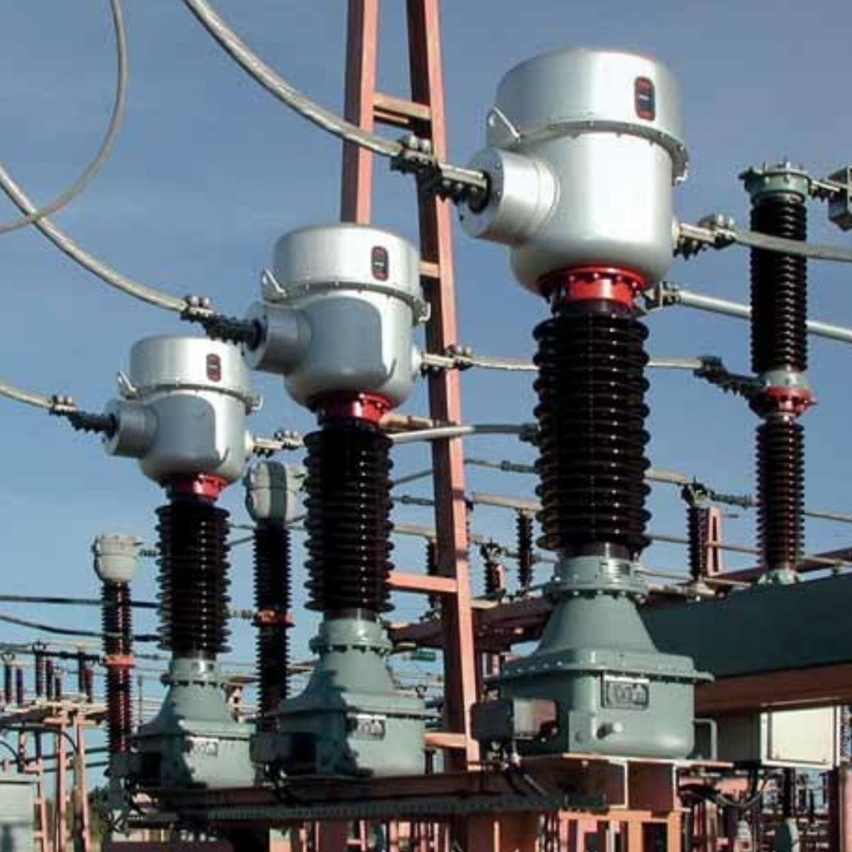
Combined transformers are precision measuring devices that combine a current transformer and an inductive voltage transformer in a single unit. Their role is to reduce the current and voltage in HV circuits to values suitable for measurement, control, and protection systems.
By electrically isolating sensitive meters, relays, and protection devices from the HV circuit, they ensure both safety and measurement accuracy. Their design is particularly beneficial in substations where limited space or high installation costs prevent the use of separate transformers.
Thanks to their high accuracy for both current and voltage, combined transformers are well suited for use at metering points. Arteche combined transformers are designed for operation in the 72.5–300 kV range.
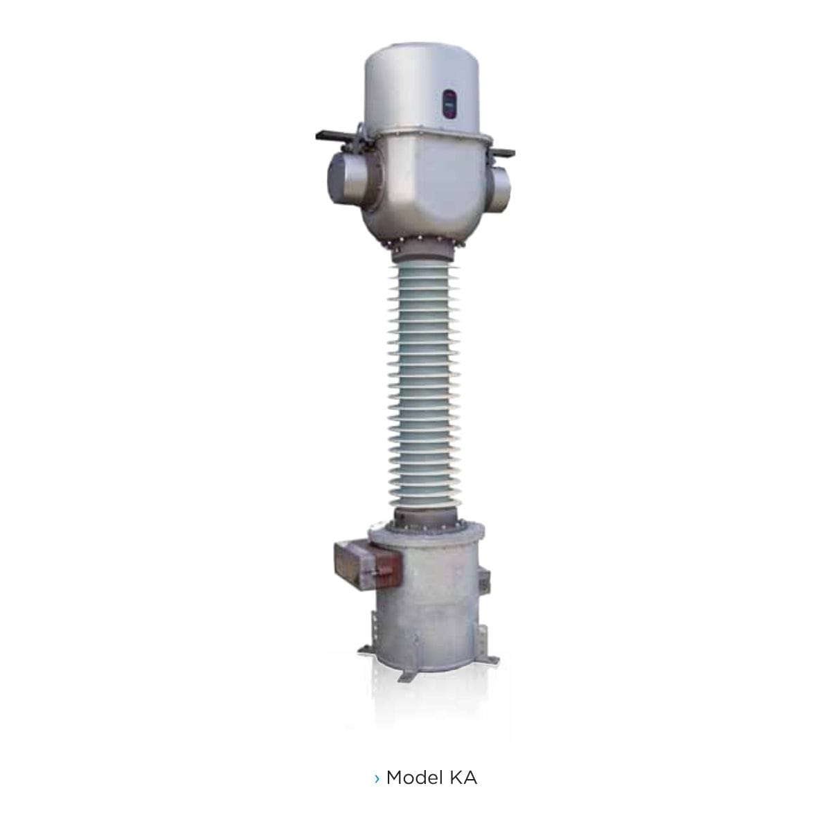
The active parts of the combined transformer are enclosed in a metal tank that provides a low-voltage shield and paper-oil insulation for high-voltage protection. The CT elements are located in the upper section, while the VT core is located in the lower section.
Depending on installation requirements, the CT primary winding may be configured as either a rod or a busbar. The secondary windings and connections are contained in a specially designed paper-oil capacitive bushing with multiple shields, ensuring optimal electric field distribution inside the device.
Both the primary and secondary windings are wound on the same core located in the center of the tank. An important feature of this design is its anti-resonance behavior, which allows the transformer to operate reliably not only at nominal frequency but also during temporary frequency deviations.
At the top, an oil volume compensation system regulates changes in oil volume due to temperature fluctuations, assisted by an indicator that simplifies oil level monitoring.
The transformer is equipped with primary terminals (P1, P2), a secondary terminal box, and a grounding terminal. The housing insulator, made of porcelain or silicone rubber, ensures strength and resistance to environmental conditions.
Advanced applications and functionality
In addition to measuring current and voltage for control and protection equipment, combined transformers are also used for advanced applications, including:
- Discharging HV lines and capacitor banks, essential for safe maintenance and network management.
- Monitoring power quality and harmonic measurement, ensuring compliance with modern grid requirements.
In addition, combined transformers play a key role in protecting high-voltage lines and substations, forming an integral part of the power system's security.
Detailed electrical parameters and accuracy classification
Measurement accuracy is critical, which is why combined transformers are designed with high accuracy classes. For current circuits, secondary windings are available for:
- Protection – including windings with linear cores and low induction.
- Precise measurement – including revenue-grade accuracy such as class 0.1/0.15.
The number of secondary windings can be tailored to customer requirements.
Voltage transformer accuracy and burden classes comply with international standards: IEC – 100 VA Class 0.2/3P and 250 VA Class 0.5/3P; IEEE – 0.3 WXYZ / 1.2 WXYZ, ZZ. Higher accuracy and burden classes are also available on request.
For current and voltage transformation, parameters such as rated primary current, rated secondary current, effective value of primary current, and rated accuracy limit factor are essential. The instrument safety factor (fs) is important for the protection of measuring devices. Accuracy is also defined by error indicators (current error, phase displacement, total error).
Testing process and quality assurance
Each combined transformer undergoes rigorous testing in accredited factory test facilities to ensure compliance with declared parameters and the highest quality standards. These include partial discharge tests, tangent delta (DDF) measurement, detailed insulation checks, and accuracy tests.
These transformers are designed to withstand all type tests required by international standards, ensuring long-term reliability under diverse operating conditions.
The products fully comply with international standards including IEC, IEEE, UNE, BS, VDE, SS, CAN, AS, NBR, JIS, GOST, and NF. Additionally, every unit is individually tested to guarantee quality and dependability.
Combined transformers are hermetically sealed and require no maintenance throughout their service life. This significantly reduces operating costs and ensures long-term, trouble-free performance.